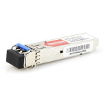
For the users who have the experience of using 1000Base-LX/LH SFP, they may be familiar with the mode conditioning patch cable (MCP cable). What’s mode conditioning patch cable? Why it is required for 1000Base-LX/LH applications? This post will give you the answers.
What’s Mode Conditioning Patch Cable?
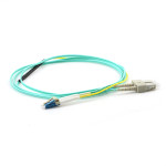
 Mode conditioning patch cable is used to adapt the single mode output of Gigabit Ethernet (1000Base-LX/LH) transceivers to a multimode applications at 1300nm wavelength. This cable is compliant with the IEEE 802.3z standard and has application in LAN (Local Area Network), Telecommunication system and MAN (Metropolitan Area Systems). All mode conditioning patch cables are made with duplex cable, with a single-mode to multi-mode offset fiber connection part in one of the two legs. This specialized cable helps avoid Differential Mode Delay (DMD) effects that (will be introduced below) can occur when long wave transceiver modules operate at both single-mode and multimode wavelengths. The mode conditioning patch cable causes the single-mode transceiver to create a launch similar to a typical multimode launch.
Why Use Mode Conditioning Patch Cables?
 As mentioned above, the requirement for mode conditioning patch cable is specified only for 1000Base-LX/LH transceivers transmitting in the 1300-nm window and in applications over multi-mode fiber. And you need to know that mode conditioning patch cable should never be used in 1000BASE-SX links in the 850-nm window. Why? Because transceiver modules used in Gigabit Ethernet (1000Base-LX/LH) launch only single-mode (1300 nm) long wave signals. This poses a problem if an existing fiber network utilizes multimode cable. Here, we need to insert a knowledge point and understand what’s DMD (different mode delay) phenomenon. When a single mode signal is launched into a multimode fiber a phenomenon known as DMD can create multiple signals within the multimode fiber. This effect can confuse the receiver and produce errors. Mode conditioning patch cable utilizes an offset between the single-mode fiber and the multi-mode fiber to eliminate DMD and the resulting multiple signals allowing use of 1000Base-LX over existing multi-mode fiber cable systems.
Structure of Mode Conditioning Patch Cable
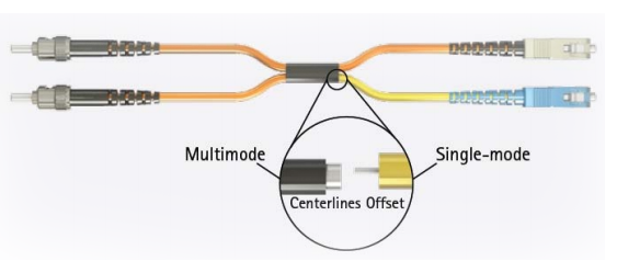
The following diagram is the structure of MCP cable. The orange legs are the multi-mode fibers while the yellow leg is the single-mode fiber. And there is a offset fiber connection part in the center to connect the legs. In general, mode conditioning patch cables can be designed with SC, ST, LC, MTRJ fiber optic connectors.

Structure of Mode Conditioning Patch Cable
Notes for Using Mode Conditioning Cables
When using mode conditioning cables to patch an existing multimode cable plant to your Gigabit LX equipment, the following things you should know:
- Mode conditioning cables are normally used in pairs. That means that you will need MCP cables at each end to connect the equipment to the cable plant. So then these cables are usually ordered in even numbers. The usual reason why someone may order one cable is so they may keep it as a spare.
- If your Gigabit LX switch is equipped with SC or LC connectors, please ensure to connect the yellow leg (Singlemode) of the cable to the transmit side, and the orange leg (multimode) to the receive side of the equipment. It is imperative that this configuration be maintained on both ends. The swap of transmit and receive can only be done at the cable plant side.
Warm Tips: For more sultions of Mode Conditionding Patch Cable & 1000Base-LX/LH transceivers or finding mode condition cable manufacturers, I recommend you to visit Fiberstore.com. A comprehensive line of High-quality MCP cables or 1000Base-LX/LH transceivers is offered by Fiberstore. Moreover, hundreds of useful tutorials and industry latest news are waiting for you.


