In the structured cabling system, patch panel serves as an important tool for good cable management, which can help to avoid fiber optic losses and troubleshoot the connection. However, each of the links is a potential point of failure. In most cases, the trouble is typically found in the connection wiring. When the connection is linked between the patch panel and switch, the failure link often lies in that the patch panel port is not working. Today’s topic will explore how to troubleshoot patch panel connections.
Deciphering Patch Panel
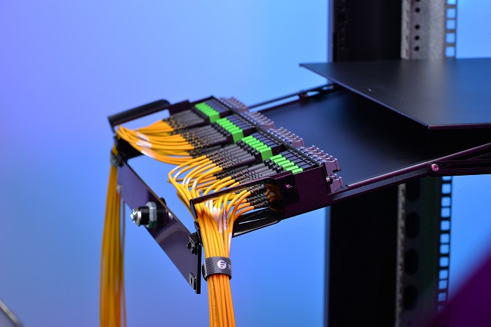
Fiber optic patch panel is a mounted hardware unit containing an assembly of port location for fiber cable management so that it is often come with rack mount enclosure. The patch panel can terminate the fiber optic cable while providing access to the individual fibers for cross connection. The significant benefit of fiber patch panel is to eliminate the cable clutter and provide port expansion for future growth. Except that, the most common connection problem is caused by excessive signal loss of its connectors or faulty connection of fiber to the patch panel.
With the same function of common fiber patch panel, the Ethernet patch panel contains several ports to connect and manage incoming and outgoing Ethernet cables. The copper patch panel is designed in different styles: punch down or feed-through type. In recent years, the feed-through patch panel is more popular in the market since it is much easier to install with the loaded RJ45 ports. With a punch down patch panel, firstly you need to terminate all cables into the patch panel. In this respect, using T568A or T568B configuration is another important considerations. Usually, the connection failure of the copper patch panel is caused by the incorrect punch-down way. For more information about how to punch down a patch panel, please refer to Should We Choose Punch Down or Feedthrough Patch Panel?
Common Causes of Connection Failure in Patch Panel
Generally, the wired connection consists of three aspects: network switch, connection wiring (patch panel is used for cabling) and network device. When the trouble is found on the aspects of the patch panel, there are several possibilities:
- The patch cables going from the switch to the patch panel
- The ports on the front of the patch panel
- The RJ45 cable going from the patch panel to the wall outlet
- The labeling of the patch panel port on the wall outlet
How to Troubleshoot Patch Panel Connections?
If the failing link is specified at the side of the patch panel, you can troubleshoot the connection problems step by step:
The visual fault locator (VFL) and OTDR are often used to troubleshoot the fault location and power meter of fiber optic cable. And the network cable tester is used for RJ45 cables.
The appropriate link mode is defined in the mated connection of modular plugs at the end of patch cords and the jacks at the patch panel. For fiber optic patch panel, there are different connector options, including SC, ST, MTP, MPO or LC fiber patch panel. So the corresponding LC, SC, ST, MTP, MPO fiber cables are needed to make a suitable connection. But for the copper patch panel, the link problem is often caused by that the patch panel is punched down incorrectly. The TIA 568A/568B wiring standard should be followed. Inappropriate cable category is also appeared in copper patch panel environment (e.g. Cat3 in a Cat5e application).
Patch panel labeling is a common way to make the troubleshooting easier. A chaotic collection of patch cords can be brought into order with properly labeled patch panels. But in the process of labeling, we can easily get it wrong in a situation where routing the cables from port to port. So cables routed to wrong connection might cause the patch panel link failure. When it is sure that no problem occurs in the mentioned above, you need to check out the labels at both ends.
Conclusion
Diagnosing the failing links of the patch panel is a decisive factor to ensure the link meets the required transmission performance. Although troubleshooting patch panel connections can often be frustrating, you will find and correct the cause of the trouble if you keep calm and be logical when problems crop up. By resolving the troubles or possible causes step by step, you can get the correct link quickly.


