If you’re a network engineer once involved in a cable plant installation project, you must have heard the term Link Budget. People in this area know how important it is to a fiber optic network cabling. During the design stage of the cabling, link budget is adopted to predict the amount of light required to ensure an uninterrupted communications link. And another closely related term is Link Loss Budget. Together they contribute to the proper operation of a fiber run.
Link budget, or power budget, refers to the amount of loss that a data link (transmitter to receiver) can tolerate in order to operate properly. Sometimes it has both a maximum value and a minimum value so that the input power at the receiver end is within its operating range.
Link loss budget is the amount of loss that a cable plant should have. It is calculated by adding the losses of all the components used in the cable plant to get the estimated end-to-end loss. Obviously, the link budget and link loss budget are related. A data link will only operate properly when the link loss is within the link budget of the link.
The difference value between the power budget and the link loss budget is known as link budget buffer. The buffer value should not be too small, because the margin for error is 3 dB in a fiber link. If the in-between components are fixed, then you can save more margin by changing the transmitter or receiver on two ends; if the two end devices are fixed, you can save yourself more margin by changing the fiber optic jumpers and other passive components.
Generally, four main parameters are used to calculate the optical transmission link budget buffer. They are minimum optical transmitter power, maximum connector insertion loss, optical fiber cable transmission loss, and maximum optical receiver sensitivity.
Transmitter power and receiver sensitivity are absolute values (e.g. mWatt or dBm, 10*log(mW) = dBm), but connector insertion loss and optical fiber cable transmission loss are relative values (e.g. % loss). The connector insertion losses comprise the connections of fiber optical jumpers, transceivers, patch panels, etc. In order to help understand how to calculate the link budget, here is an example of a typical 2-kilometer multimode link with 5 connections (2 connectors at each end and 3 connections at patch panels in the link) and one splice in the middle. The maximum fiber loss of multimode fiber is 3.5 dB/km and the maximum acceptable connector insertion loss is 0.75 dB. Typical splice loss for multimode fiber is 0.3 dB. Therefore, the total maximum link loss is 11.05 dB.
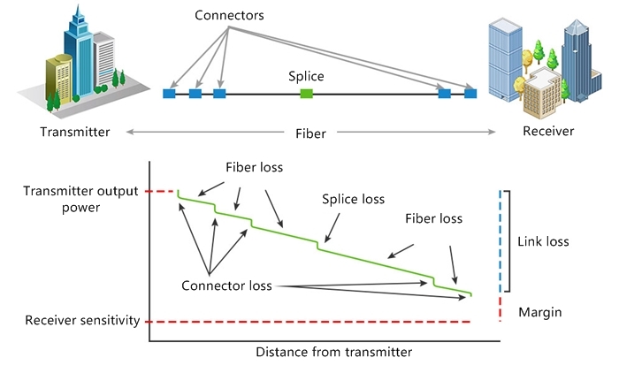
Figure: the link budget and link loss illustration of a typical 2-kilometer multimode fiber link.
Table 1: calculation of link budget and link loss.
| Absolute Values | Relative Values | ||
| Minimum transmitter power (Tx) | -5 dBm | Optical fiber cable transmission loss | 7 dB |
| Maximum receiver sensitivity (Rx) | -21 dBm | Maximum connector insertion loss | 3.75 dB |
| Typical multimode fiber splice loss | 0.3 dB | ||
| Maximum transceiver link budget | 16 dB | Maximum link loss along the fiber run | 11.05 dB |
| Network segment link budget buffer = 4.95 dB | |||
Yes. Different fiber cable types have different fiber loss at their working wavelengths. According to TIA-568-C.0- 2 standards, their maximum values are as below:
Table 2: maximum loss values of multimode fiber and single-mode fiber.
| Fiber Type | Multimode | Single-mode | |
| Wavelength (nm) | 850 | 1310 | 1550 |
| Fiber Loss/km (dB) | 3.5 | 0.4 | 0.3 |
| Insertion Loss (dB) | 0.75 | 0.75 | 0.75 |
If you want to add more connections in the link when the two absolute values are known, the simplest way is to choose fiber optic jumpers with low insertion loss as much as possible. Because the connector insertion loss contributes a lot to the total link loss in a fiber link. You can also use more precise splice machines but it is not as easy as using lower loss fiber optic jumpers.
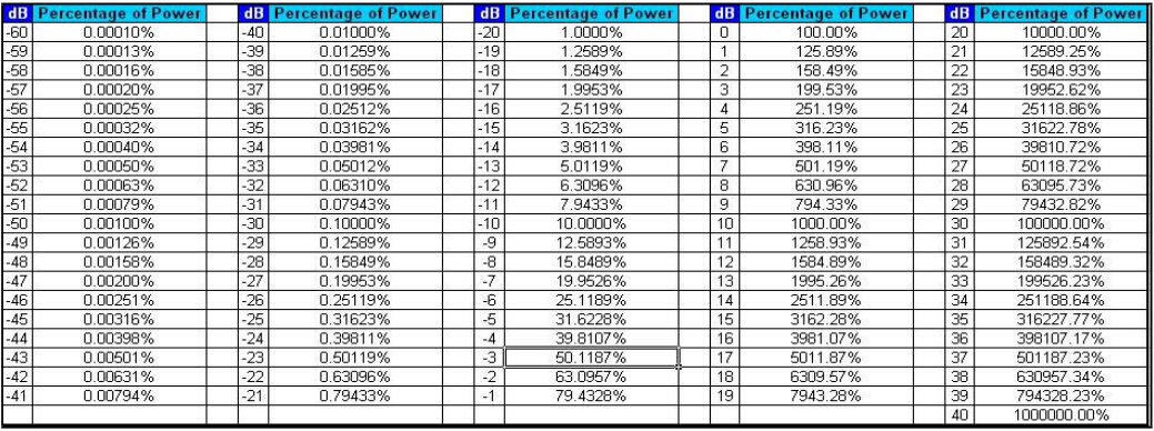
The table below shows the amount of loss and the percentage of light remained. 20 dB of loss equals a loss of optical power in a system of 99%. And 30 dB of loss equals 99.9% of loss. 30 dB is typically the most loss a communications system can have since 10-10 error count cannot be factored with less than 0.1% of light.
Table 3: the amount of loss and the percentage of light remained.
Link budget and link loss budget are both vital analysis measures in fiber optic network design. The link budget is mainly used before the installation, whereas link loss budget is used before and after the installation. After the cable plant is installed, the calculated loss values are compared with the test results to ensure the link can operate properly.
Related Article: How to Reduce Various Types of Losses in Optical Fiber?