The WDM (Wavelength Division Multiplexing) transponders, also called O-E-O (optical-electrical-optical) wavelength converters are widely deployed in a variety of networks and applications nowadays, especially the in WDM networking system. In the previous article “What’s the Difference Between Transceiver & Transponder?“, we have learned that the basic concept about the transponder and make clear the difference with transceiver. Today, I am going to talk about the applications of WDM transponders through several practical cases.
WDM transponder is an optical-electrical-optical (O-E-O) wavelength converters that are designed to perform an O-E-O operation to convert wavelengths of light. Figure 1 shows bidirectional transponder operation (the transponder is located between a client device and a DWDM system). From left to right, the transponder receives an optical bit stream operating at one particular wavelength (1310 nm). And then it converts the operating wavelength of the incoming bitstream to an ITU-compliant wavelength and transmits its output into a DWDM system. On the receive side (right to left), the process is reversed. The transponder receives an ITU-compliant bit stream and converts the signals back to the wavelength used by the client device.
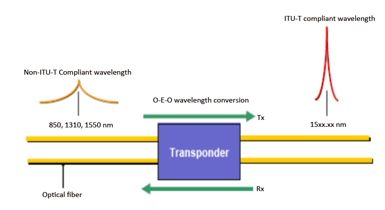
Figure 1. WDM Transponder Working Principle
As above mentioned, the WDM transponder is widely used in many networks and applications. Here are three classical application schemes of the WDM transponders.
As we know, multimode fiber (MMF) is used for short-distance transmission while single-mode fiber (SMF) is used for longer-distance transmission. Mode conversion is required in the network since the network distance requires to exceed the limit of MMF or in the case that equipment is designed with multi-mode port but connectivity is required to single-mode equipment. As Figure 2 shown, two switches are connected by the WDM transponders which convert the MMF to SMF, enabling the network connectivity across the distance between the switches.
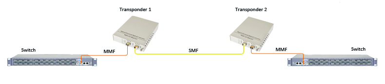
Figure 2. Multimode to Single-Mode Fiber Conversion
In addition, the 10G transponder can also be used between a 10G SFP+ DAC (Direct Attach Copper) cable to an SMF. As Figure 3 shown, a 10m 10G SFP+ DAC cable is used to connect the 10G switch port to the transponder (in the left location); A pair of multimode SFP+ transceivers provide the connectivity between the transponder and the 10G switches (in the right location). This solution is ideal for the application which requires to connect switches exceeds the distance limitation (10 meters) of 10G DAC cable.
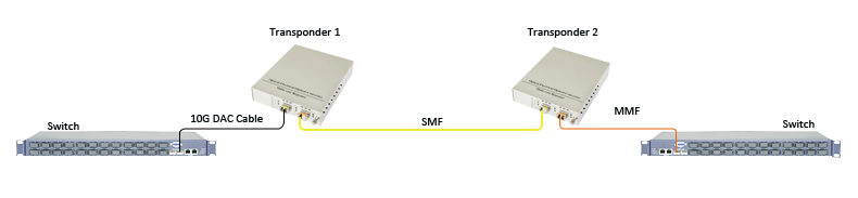
Figure 3. 10G DAC to Single-Mode Fiber to Multi-mode Fiber Conversion
Dual fiber transmission and single fiber transmission are two transmission modes applied in the network. Depending on the type of equipment and the fiber installed facility, dual fiber to single fiber conversion is required sometimes. Here are two situations:
In this case, two dual fiber switches are connected with a single fiber via two transponders. The single fiber is single-mode fiber (1310/1550 nm) and operates with BiDi (bi-directional) wavelengths. See Figure 4.
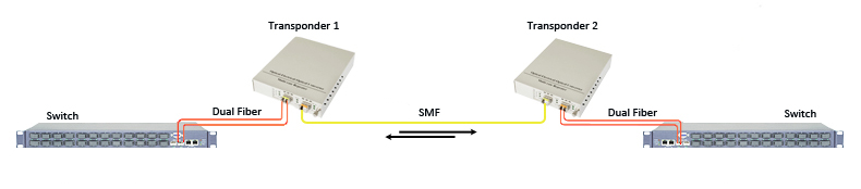
Figure 4. Dual Fiber to Single Fiber Conversion
Dual fiber uses the same wavelength over two different strands of fiber—one strand as Transmit (Tx) and the other as Receiver (Rx). See Figure 5.
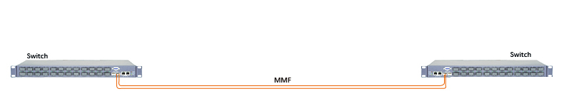
Figure 5. Traditional Dual Fiber Connection
By converting the dual fiber to single fiber, the network can double the capacity of the existing infrastructure, as Figure 6 and 7 shown.
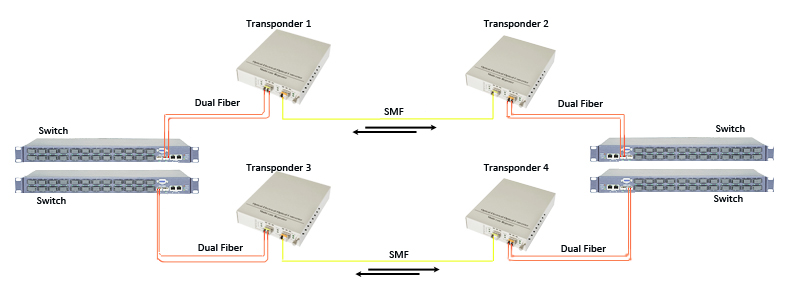
Figure 6. Double Fiber Capacity With Dual Fiber to Single Fiber Conversion (two links)
In this application, two other switches are added to each link. The transponder doubles the capacity of the dual fiber link by converting each strand from a dual fiber link to a BiDi single fiber link.
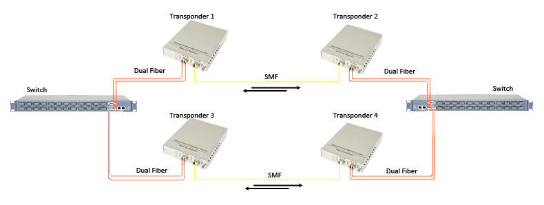
Figure 7. Double Fiber Capacity With Dual Fiber to Single Fiber Conversion (single link)
In this case, the transponder doubles the capacity of two dual fiber links by converting each strand of the dual fiber to two BiDi single fiber link, providing redundancy protection between the two switches.
Wavelength conversion is the most common application of a WDM transponder. Fiber network equipment with fixed fiber interfaces (ST, SC, LC FC, etc.) operating over legacy wavelengths (850 nm, 1310 nm, 1550 nm) must be converted to CWDM (Coarse Wavelength Division Multiplexing) or DWDM (Dense Wavelength Division Multiplexing) wavelengths via a WDM transponder which is to automatically receives, amplifies, and then re-transmits a signal on a different wavelength without altering the data/signal content. As Figure 8 shown, a 10G switch with signal output at 1310 nm is required to link to a CWDM Mux/DeMux channel port (1610nm wavelength). A transponder configured with a standard SMF SFP+ and a 1610nm CWDM SFP+ is used between the switches and CWDM Mux/DeMux, achieving the wavelength conversion.
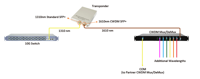
Figure 8. Wavelenth Conversion in CWDM System
After learning the above contents, we know that WDM transponders can be used in mode conversion, dual to single fiber conversion as well as wavelength conversion. When using the WDM transponders, you should note the following point:
- It is not necessary to use the transponder for single wavelength transmission;
- The number of transponders used in the network depends on your actual network plan;
- You should choose the corresponding transceivers and line card to configure the transponder according to your requirement.