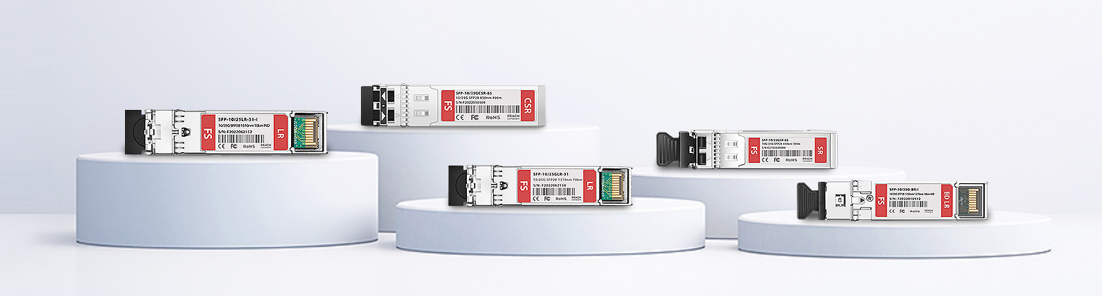
What is a 25G CWDM Transceiver?
The 25G CWDM transceiver plays a crucial role in modern telecommunications, particularly in 5G fronthaul networks. Operating at 25 Gbps, it utilizes CWDM technology to transmit multiple signals over one fibre, optimising bandwidth. Specifically designed for 5G fronthaul, it supports 25G Ethernet and CPRI/eCPRI, with impressive 10km link distances over single-mode fibre. Fully compliant with SFP28 MSA, CPRI, and eCPRI standards, it typically operates within the wavelengths of 1270nm-1370nm and 1470nm-1570nm.
If you want to know more about the differences between the 25G CWDM module and other 25G SFP28 modules, you can check out this article: 25G SFP28 Transceiver Module Overview.
What is the 5G Transport Network?
The 5G transport network encompasses fronthaul, midhaul, and backhaul, connecting cell sites with one another, then with the core network, and ultimately with data centres.
Fronthaul
As 5G technology continues to evolve, the significance of “fronthaul” in the telecommunications industry is on the rise. This fiber-based link, integrated within the Radio Access Network (RAN) infrastructure, plays a pivotal role in achieving faster speeds and reduced latency. With the introduction of Distributed RAN (DRAN) and Centralized RAN (CRAN) approaches, base station components such as the Central Unit (CU), Distributed Unit (DU), and Active Antenna Unit (AAU) are undergoing substantial restructuring to meet evolving requirements. Fronthaul acts as the vital connection between the active antenna unit (AAU) and the distributed unit (DU), ensuring smooth communication and efficient data transmission. Innovations like the 25G CWDM SFP28 transceiver are essential for facilitating seamless communication and efficient data transfer across 5G fronthaul networks.
Midhaul
Midhaul is a vital element of the telecommunications network, acting as the intermediary between the fronthaul and backhaul segments. It encompasses the transmission path from the Distributed Unit (DU) to the Centralised Unit (CU). In the context of 5G networks, base stations are structured into a distributed architecture. Here, the DU oversees the transmission and reception of wireless signals, while the CU manages communication with the core network. Acting as a pivotal link between these two units, midhaul facilitates the transfer of data from the DU to the CU for further processing and dissemination across the network.
Backhaul
In addition to fronthaul and midhaul, the 5G transport network also includes the backhaul. This component consolidates access to traffic from the Radio Access Network (RAN) and utilises various technologies such as Ethernet, microwave, and optical fibre to transport it to the central office or data centre. The backhaul serves as a crucial link, connecting the fronthaul and midhaul to the core network, facilitating seamless data transmission across extensive distances.

Utilisations of 25G CWDM Transceivers
In the initial stages of setting up 5G networks, fronthaul predominantly relies on direct fibre links, along with extensive coverage of both high-frequency and low-frequency spectrums for additional access points. To optimise the utilization of existing fibre resources, CWDM optical modules play a crucial role. The 25G CWDM solution allows for the selection of 6 or 12 wavelengths from the 18 specified in the ITU-T G.694.2 standard, spanning from 1271nm to 1611nm. Adhering to this standard enables optical transmission equipment from various vendors to operate harmoniously within the same network, ensuring network stability and reliability while mitigating issues stemming from equipment mismatches.
- 25G CWDM SFP28 6-Wavelength Solution
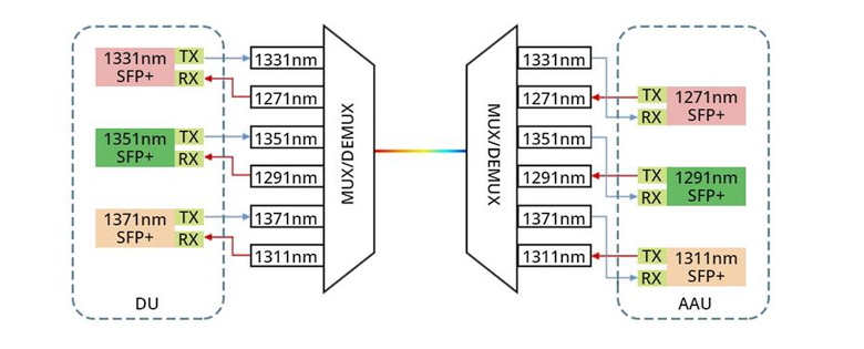
The 6-wavelength 25G CWDM solution opts for the initial 6 shorter wavelengths (1271nm~1371nm) due to the maturity of the industry chain and the lesser impact of transmitter dispersion penalties (TDP). It’s widely agreed upon that the AAU side utilizes wavelengths of 1271nm, 1291nm, and 1311nm, while the DU side employs wavelengths of 1331nm, 1351nm, and 1371nm, as depicted in Fig.3. Additionally, the optical module on the AAU side requires cooled directly modulated lasers (DMLs) to meet industrial-grade standards.
- 25G CWDM SFP28 12-Wavelength Solution
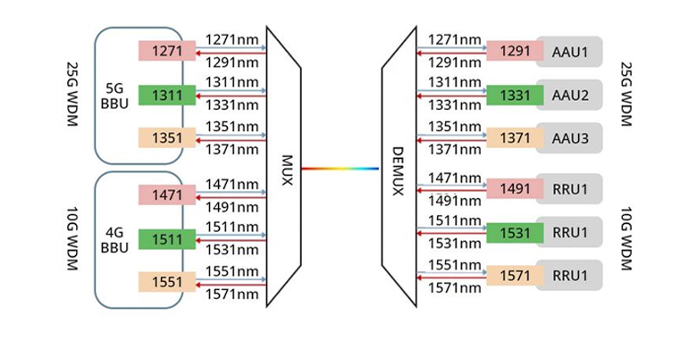
The 12-wavelength 25G CWDM solution addresses a mixed transmission scenario involving both 4G and 5G networks. To enhance reliability and reduce component costs, the wavelengths ranging from 1271nm to 1371nm operate at a 25Gbit/s data rate for 5G fronthaul networks, while the wavelengths from 1471nm to 1571nm operate at a 10Gbit/s data rate for 4G fronthaul networks. This arrangement, illustrated in Fig. 4, facilitates the smooth transition from 4G to 5G base stations. However, in practice, the 25G SFP28 connector takes precedence due to its compatibility with both 4G and 5G networks, making the 12-wavelength solution less commonly used in real-world scenarios.
Benefits of 25G CWDM Transceivers
- Cost-effectiveness CWDM technology enables the transmission of multiple signal wavelengths over the same fibre optic cable, efficiently utilising fibre optic resources. With 25G CWDM optical modules, multiple data streams can be transmitted over a single fibre optic cable without the need for additional fibres, thus conserving fibre optic resources and reducing network construction costs.
- Flexibility and Scalability Given the significant and ever-growing volumes of data typically associated with big data applications, networks must possess robust flexibility and scalability. By utilising 25G CWDM modules, users can dynamically select different wavelengths for data transmission, enhancing the adaptability and scalability of the network to meet the continuously expanding demands of big data processing.
- Data Security In the realm of big data applications, the handling and processing of extensive volumes of sensitive data are routine, emphasising the critical importance of data security. 25G CWDM modules enhance data transmission security by segregating data streams of varying wavelengths into separate channels. This segregation reduces the risks of data leaks and interference, thereby enhancing the reliability and security of data transmission.
Conclusion
In brief, the 25G CWDM SFP28 is a critical optical transceiver that efficiently sends multiple signals down a single fibre optic cable using CWDM technology. It plays a pivotal role in providing effective data transmission solutions for 5G fronthaul networks. This technology not only optimizes how bandwidth is used but also meets the high-speed and low-latency demands of 5G networks. Moreover, it enhances data transmission security by segregating data streams into separate channels based on different wavelengths. Overall, its use ensures comprehensive protection for network performance, flexibility, and security, laying a solid foundation for the future of 5G communication.
Related Articles: