Read by the microcontroller optical modules and CDR-related memory, and in accordance with the parameters that need to be read LCD display real-time, so that the results intuitive and easy to understand. While connected via serial port and external facilitate debugging. In this system, SFP module implemented by CDR I2c bus communication with the microcontroller. fiber optic transceiver module via an external device access signal, the photovoltaic modules into an electrical signal, and then after the clock data recovery CDR, bit error rate, measuring extinction ratio, sensitivity and other parameters with normal test results to see whether the correct comparison. While the optical module is connected via the optical interface with external microcontroller to communicate with the outside world through the serial port for data exchange, each signal via SMA connector leads, as required by coaxial cable to connect the debugger, it is easy to debug.
SFP Module Monitoring Platform Software Design
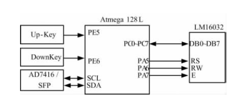
Software system design structure with a brief description of the microcontroller Atmega128L LCD (Model LM16032) using parallel data transfer, three control bit MCU PA5 ~ 7 and LCD (RS, RW, E) is connected, plus two control LCD display on the Up-key and turn the key down key DownKey and SCM PE5 and PE6 connected to the microcontroller interrupt the way to achieve the appropriate control. SFP microcontroller reads the data from the relevant parameters I2c bus after transmission through parallel to the LCD display. Using the timer mode, so With a frequency greater than 24MHz refresh LCD display.
SFP Module Main Parameters Read
Temperature parameters read
Because of the module can be used in a high rate of system and has the appearance of small, the layout of the they are usually very compact.In these applications sfp transceiver of rectangular box shape affect the cooling air flow, thus partially weaken the advantages of easy to use, so the temperature inside the module as a useful parameter to measure the long-term stability of the device and device of electro-optic specifications conform to the degree of life.3.2 read voltage parameterIn the SFP working voltage can through sensor installed on the internal PCB circuit for measuring.These measurements can also be used to observe the working voltage drift.And according to the experience can be linked with a given SFP pin or monitoring failure due to the system power supply environment caused by the large voltage fluctuation.
Read bias current
When reliability prediction has been the most effective transceiver module parameter is the laser bias current, typically used in integrated optical transceiver modules are in constant optical output power mode. Through a closed loop feedback circuit to change the laser bias current so as to stabilize the laser output power. Since the laser efficiency and the threshold values are changed with temperature, and many modules are required to change the laser bias current so as to stabilize the optical output power of the laser, the laser bias current if the variation is not as temperature or voltage changes caused, it shows that the laser potential stability problems.
Based on the Test Platform Module Parameters
Bit Error Rate Test
For error test mainly through error instrument, optical module, and the CDR from ring, through error instrument observation error rate is less than 1 hour 10-12.Test procedures and results:
(1) good connection test equipment.
(2) the work continuously for an hour, once every five minutes record error rate.
(3) the bit error rate has been less than 10-12.