With the demand for higher bandwidth, faster speeds and optimal applications, equipment architecture trends have changed from traditional 3-tier architecture model to leaf spine architecture in existing data centers. 3-tier architecture vs. leaf-spine architecture: which is better? What should be considered when deploying one network architecture over the other?
3-Tier Architecture vs. Leaf Spine Architecture
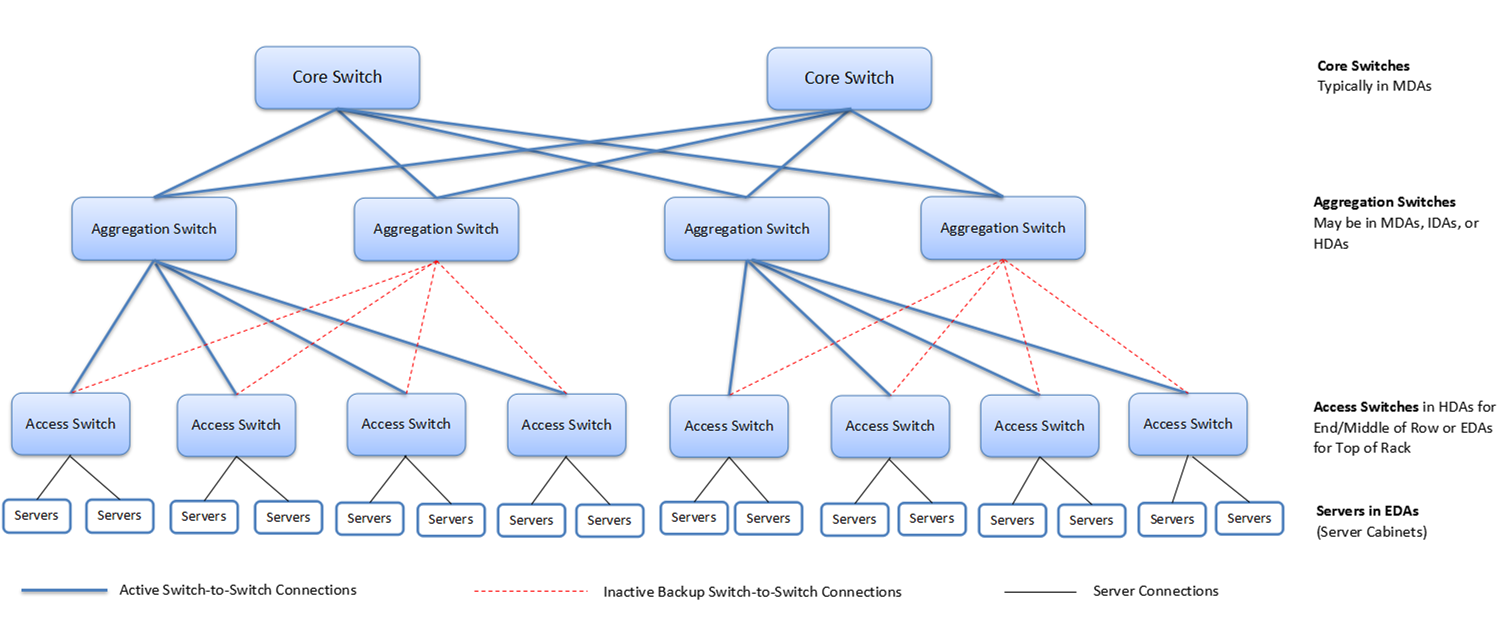
The traditional 3-tier architecture model is designed for use in general networks, usually segmented into pods which constrained the location of devices such as virtual servers. 3-tier architecture consists of core switches, aggregation/distribution switches and access switches. These devices are interconnected by pathways for redundancy which can create loops in the network. As part of the design, a protocol (Spanning Tree) that prevents looped paths is implemented. However, doing so deactivates all but the primary route. A backup path is then only brought up and utilized when the active path experiences an outage. The 3-tier architecture comes with a number of disadvantages, such as higher latency and higher energy requirements.
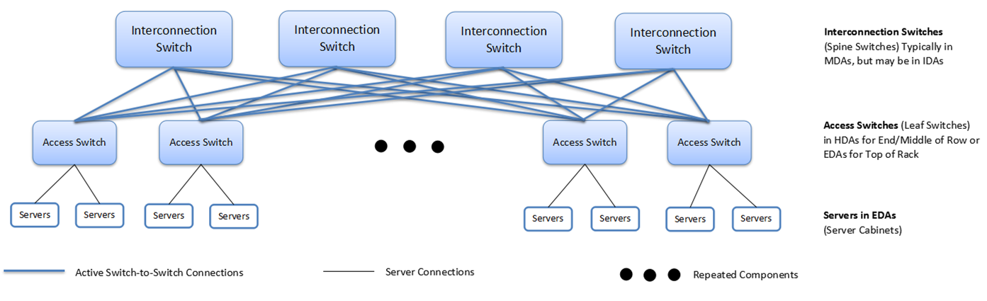
 Leaf-spine architecture, also called fat-tree architecture, is one of the emerging switch architectures that are quickly replacing traditional solutions. It features multiple connections between interconnection switches (spine switches) and access switches (leaf switches) to support high-performance computer clustering. The role of the leaf is to provide connectivity to the endpoints in the network, including compute servers and storage devices or any other networking endpoints—physical or virtual, while the role of the spine is to provide interconnectivity between the leafs. The requirements applying to the leaf-spine topology include the following:
- Each leaf connects to all spines in the network.
- The spines are not interconnected with each other.
- The leafs are not interconnected with each other for data-plane purposes. (The leafs may be interconnected for control-plane operations such as forming a server-facing vLAG.)
Compared to the traditional 3-tier architecture, the leaf-spine architecture design drastically simplifies cabling needs, especially when looking at fiber optic connectivity. But some design considerations for leaf spine architecture should be considered, which will be introduce in the next part.
Design Considerations for Leaf-Spine Architecture
Oversubscription Ratios — Oversubscription is the ratio of contention should all devices send traffic at the same time. It can be measured in a north/south direction (traffic entering/leavign a data center) as well as east/west (traffic between devices in the data center). Current modern network designs have oversubscription ratios of 3:1 or less, which is measured as the ration of downlink ports (to servers/storage) to uplink ports (to spine switches). For example, a 64-port network switch should equate to 48 ports down to 16 ports up.
Leaf and Spine Scale — As the endpoints in the network connect only to the leaf switches, the number of leaf switches in the network depends on the number of interfaces required to connect all the endpoints. The port count requirement should also account for multihomed endpoints. Because each leaf switch connects to all spines, the port density on the spine switch determines the maximum number of leaf switches in the topology. A higher oversubscription ratio at the leafs reduces the leaf scale requirements, as well.
The number of spine switches in the network is governed by a combination of the throughput required between the leaf switches, the number of redundant/ECMP paths between the leafs, and the port density in the spine switches. Higher throughput in the uplinks from the leaf switches to the spine switches can be achieved by increasing the number of spine switches or bundling the uplinks together in port-channel interfaces between the leafs and the spines.
10G/40G/100G Uplinks From Leaf to Spine — For a leaf-spine network, the uplinks from leaf to spine are typically 10G or 40G and can migrate over time from a starting point of 10G (N x 10G) to become 40G (N x 40G). An ideal scenario always has the uplinks operating at a faster speed than downlinks, in order to ensure there isn’t any blocking due to micro-bursts of one host bursting at line-rate.
Layer 2 or Layer 3 — Two-tier leaf-spine networks can be built at either layer 2 (VLAN everywhere) or layer 3 (subnets). Layer 2 designs allow the most flexibility allowing VLANs to span everywhere and MAC addresses to migrate anywhere. Layer 3 designs provide the fastest convergence times and the largest scale with fan-out with ECMP (equal cost multi pathing) supporting up to 32 or more active spine switches.
Summary
It is important to understand the 2-tier leaf spine architecture as it offer unique benefits over the traditional 3-tier architecture model. With easily adaptable configurations and design, leaf-spine has improved the IT department’s management of oversubscription and scalability. Deploying leaf-spine network architecture and buying high-performance data center switches are imperative for data center managers as leaf-spine environment allows data centers to thrive while accomplishing all needs and wants of the business.