There are some different ways to set up a network connection, but the most reliable way is to use both the router and the switch. Well, do you know the right router to switch connection diagram? This article will give a clear explanation for the router, the switch and the router to switch connection diagram.
What Are Switch & Router?
The network switch is commonly applied in campus environments, business and other large networks. Usually, it works at the data link layer (layer 2) or the network layer (layer 3) of the OSI (Open Systems Interconnection) model. Therefore, it can support multiple packet protocols. As a multi-port network bridge, the network switch provides various ports for subnets to connect computers, cameras, printers, etc. Through these ports, the data packets can be sent and received between LAN segments.
Router, sometimes called Gateway, is a hardware device usually applied in home and small business networks. Based on layer 3 information of the OSI model, router functions to route packets or traffic by using IP address. This enables the network to go across different protocols.
Network switch and router both are broadly deployed in network data transmission but they definitely have some differences. Generally, they have three key differences. Firstly, routers typically use software to route. While network switches route packets on ASCI (Application Specific Integrated Circuit) hardware. Another difference is that network switches route packets faster than routers. In addition, based on IP addresses, routers can support numerous different WAN technologies. However, network switches lack some QoS (Quality of Service) features. Actually, the best way to set up a network connection is to use a router and switch in combination.
How to Connect a Switch to a Router?
Conventionally, the router is the first thing you will set up in the LAN. Since the Fiber Optic Service (FiOS) is now widely provided by many Internet providers, a modem should be connected after the router. It turns the digital signal to electrical signals, then these signals can be transmitted over Ethernet cables. Usually, a network firewall is between the internal network and the router so that all flows in and out can be filtered. However, most of the routers include the firewall feature. So there is no need for you to buy a firewall additionally. Then the switch follows. This is the general router to switch connection diagram and the following are the detailed steps to connect a switch to a router.
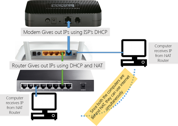
Figure 1: Router to switch connection diagram
1. Unplug the power supplies of all the devices you will connect, including cable modem, wireless router, and the switch. And unplug any Ethernet cables that are plugged into any of them.
2. Connect telephone wire with the modem and connect an Ethernet cable to the port on the back of the modem.
3. Connect the other end of Ethernet cable connected with modem into WAN port of the router.
4. Connect an Ethernet cable to one of the numbered ports on the switch, then connect the other end to a wired device such as a computer or a gaming console.
5. Connect another Ethernet cable to one of the ports on the back of the switch and connect the other end to the port at the back of the modem.
6.Power on the router, modem, Ethernet switch, and the devices connected to the switch. After several minutes, the connection is ready to go.
Summary
After reading this article, you may clear about the right router to switch connection diagram and the proper way to connect them step by step. For suitable switches with high-quality such as 1GB Ethernet switch, 10GB Ethernet switch, 40GB Ethernet switch, or 24-port switch, 48-Port Gigabit switch and so on, FS will be your ideal choice.
Related Article: Network Switch vs Network Router vs Network Firewall