The boosting global data traffic spurs the demand for faster data transmission and greater capacity over the network, and the demand is not gonna slack. Thus migration from 10G to higher speed 40G or 100G becomes an inevitable trend yet a necessity for network managers to accommodate the data boom. For 40G short-reach data communication and interconnect applications, 40G QSFP SR4 and 40G QSFP BiDi transceiver modules are generally involved. This article guides you through the working principles of the two 40G transceivers, and then presenting the cabling options for each.
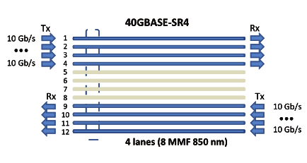
Before we go any further, it’s better to first obtain some basic information about 40G QSFP SR4 and 40G QSFP BiDi transceiver. As they both used to support short-range (SR) 40G connectivity, the major difference lies in the protocols, namely the way to achieve data transmission for 40G application. 40G QSFP SR4 operates over MMF ribbon with MPO connectors, utilizing 4 parallel fiber pairs (8 fiber strands) at 10Gbps each for a total of 40Gbps full duplex.
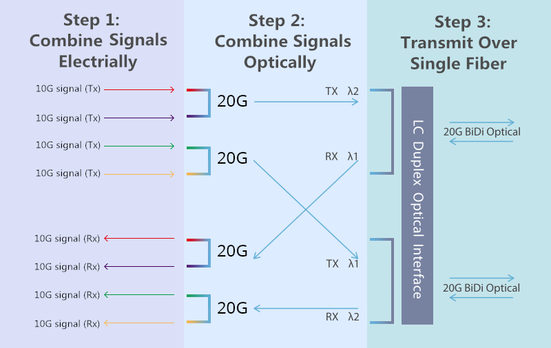
40G QSFP BiDi uses the same 10-Gbps electrical lanes, however, they are combined in the optical outputs. Thus requiring two fibers with a LC connector interface. Each fiber simultaneously transmits and receives 20-Gbps traffic at two different wavelengths. Which means that 40G QSFP BiDi module converts four channels each of 10Gbps transmit and receive signals to two bidirectional channels of 20Gbps signals. The connection can reach 100 m on OM3 MMF or 150 m on OM4 MMF, which is the same as 40-Gbps SR4.
Whether for 40G QSFP SR4 or BiDi Transceivers, there basically exist three cabling approaches: direct connection, interconnection and cross-connection. This section respectively illustrates the three approaches for 40G transceiver cabling.
40G SR4 operates over 12-fiber strands terminated by MPO-12 connectors, 8-fiber strands carry traffic and 4 are unused. So there are three cabling options for parallel 40G QSFP SR4 connectivity:
- Solution 1: No conversion and uses traditional 12-fiber MTP connectivity.
- Solution 2: Use conversion module. Converts two 12 fiber links to three 8 fiber links through a conversion patch panel.
- Solution 3: Converts two 12-fiber links to three 8-fiber links through a conversion assembly and standard MTP patch panels.
Here we offer cabling options for parallel 40G QSFP SR4 transceiver based on these three solutions.
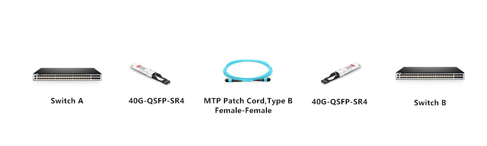
Direct connection between two parallel optics 40G Ethernet transceiver, a Type-B (key up to key up) MTP patch cable should be used. With fiber 1 on one end goes to fiber 12 on the other end, this reverse fiber positioning ensures the signal to flow from transmission on one end of the link to reception on the other end. The picture below shows an MTP patch cable directly connects two switch ports.
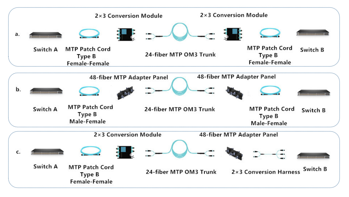
The most basic structured cabling solution is an interconnect. The following picture shows several interconnect approaches with various patch panel options.
a. The 2×3 conversion modules allow 100% fiber utilization and constitute the most commonly deployed method. It also greatly reduced jumper complexity. The female to female Type-B polarity cable here is used to directly connect two parallel optic transceivers. That same jumper is used on both ends of the interconnect link, thus eliminating concerns about correct pinning.
b. The same trunk used in method a is adopted, but the jumper type is now male to female Type-B polarity. Thus, when you install the MTP patch cable, you would install the male end in the patch panel, and you would install the female end in the electronics.
c. This combined solution might be deployed when cabling between a spine switch, where the module is placed, and a ToR leaf switch, where the conversion harness and MTP adapter panel are located.
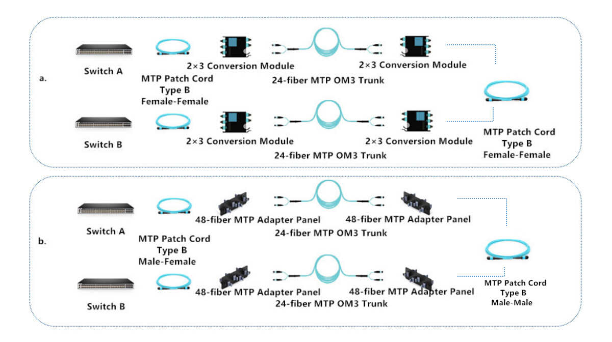
The picture below shows two cross-connection link designs for cabling a 40G QSFP SR4 transceiver.
a. This link design shows a conversion module example, which again is the most common and preferred method. All the three jumpers in the link are female to female MTP patch cable with Type-B polarity. Thus, in a conversion module deployment, only one jumper type is used for a direct-connect, interconnect, or cross-connect cabling scenario.
b. Standard MTP patch panels are deployed in this method. Here the MTP patch cables at the electronics are female (into the electronics) to male (into the patch panel), although the patch cords at the cross-connect are male-to-male going into the patch panel.
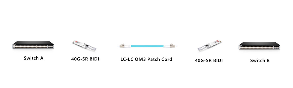
Cabling for 40G QSFP BiDi transceiver is relatively easy. Three methods are presented here.
In an unstructured cabling system, devices are directly connected with fiber optic cable. This direct-attachment design can be used to connect devices within short distances in a data center network. Direct connection between two 40-Gbps devices can be provided by MMF cables with QSFP BiDi transceivers at two ends.
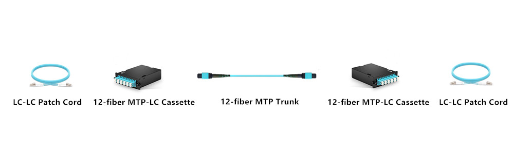
When it comes to structured cabling, more permanent links should be considered. The interconnection link between two 40G bidirectional ports basically consists of an MTP trunk, MTP module cassettes and LC fiber patch cables. Future migration can be achieved simply by changing the patch panels on each end, without the need to disrupt the cabling infrastructure.
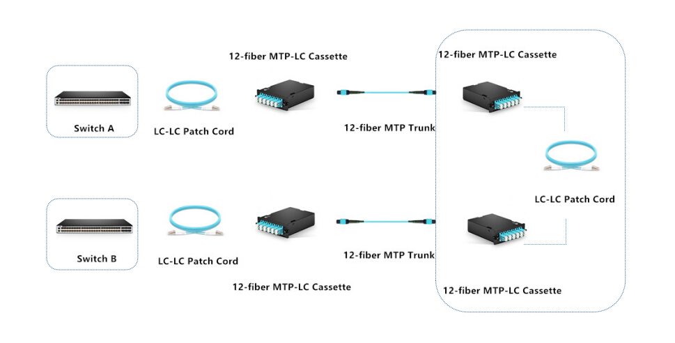
The cross-connection design involves two structured cabling links, which connect two switches via a centralized cross-connect. This design delivers much flexibility when new equipment need to be installed: only patch cables are required to make the connection from the equipment to the patch panels.
Judging from the cabling solutions for 40G QSFP SR4 and BiDi transceivers, it is clear that QSFP BiDi transceivers provide immense flexibility and simplicity compared to parallel 40G QSFP SR4 transceivers, while removing cost barriers for migration from 10G to 40G in data center networks. However, the main advantage of 40G SR4 transceiver over 40G BiDi transceiver is the reach. Hope what we discussed in the article could help make an informed decision.
Related Article: 40G Transceiver Module: QSFP+ Module And CFP Module