To meet the rapid increasing demand for higher bandwidth, the IEEE 802.3ba committee ratified the 40 Gigabit Ethernet standard and along with the general specification, defining a number of fiber optic interfaces. These standard interfaces attempted to satisfy a number of different objectives including support for multimode fiber (MMF) and single mode fiber (SMF) compatibility. The QSFP+ pluggable interface is an industry standard—Multi-source Agreement (MSA) for pluggable 40 Gigabit Ethernet optics. And there are basic three 40G QSFP+ Optics for this standard: 40G LR4 QSFP+ transceiver, 40G SR4 QSFP+ transceiver and 40G LR4 parallel single mode (PSM) transceiver. This article will have an overview of these 40G QSFP+ Optics respectively.
40G LR4 QSFP+ Transceiver
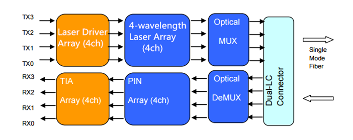
Conforming to the 802.3ba (40GBASE-LR4) standard, the 40G LR4 QSFP+ transceiver together with the LC connector can support an optical link length up to 10 kilometers over single mode fiber. 40G LR4 QSFP+ transceivers offer 4 independent transmit and receive channels. And to realize the function of transmitting the 4-channel signals over the single mode fiber, this kind of transceiver has to introduce MUX/DEMUX to multiplex/de-multiplex optical signals.
The working principle of this kind of QSFP+ transceiver is : In the transmit side, four 10 Gbp/s serial data streams are passed to laser drivers. The laser drivers control directly modulated lasers (DMLs) with wavelengths. the output of the four DMLs are optically multiplexed to a single-mode fiber through an industry-standard LC connector. In the receive side, the four 10 Gbp/s optical data streams are optically de-multiplexed by the integrated optical demultiplexer; then, each data steam is recovered by a PIN photodetector/transimpedance amplifier and passed to an output driver. The following figure shows the functional block diagram of the 40G LR4 QSFP+ transceiver.
40G SR4 QSFP+ Transceiver
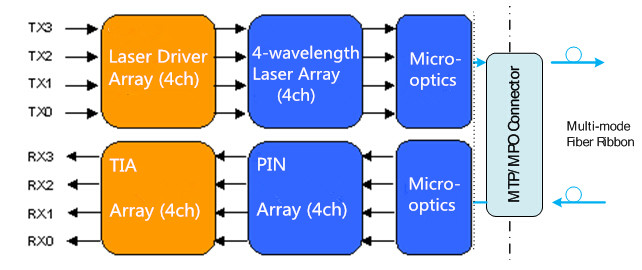
The 40G SR4 QSFP+ Transceiver (e.g. Cisco QSFP-40G-SR4), conforming to the 802.3ba (40GBASE-SR4) standard, provides a 40G optical connection using MPO/MTP fiber ribbon connectors. Unlike the 40G LR4 QSFP+ transceiver, this kind of transceiver are used together with multi-mode fiber, supporting with a link length up to 100 meters on OM3 cable and 150 meters on OM4 cable.
The operating principle of the 40G SR4 QSFP+ Transceiver is : the transmitter converts parallel electrical input signals into parallel optical signals through the use of a laser array. Then the parallel optical signals are transmitted parallelly through the multimode fiber ribbon. Reversely, the receiver converts parallel optical input signals via a photo detector array into parallel electrical output signals. The following figure shows the functional block diagram of the 40G SR4 QSFP+ Transceiver.
40G LR4 PSM Transceiver
The 40G LR4 PSM transceiver is designed with form factor, optical/electrical connection and digital diagnostic interface according to the QSFP+ MSA. As a highly integrated 4-channel optical module, this kind of transceiver can provide increased port density and total system cost savings. 40G LR4 PSM transceivers supports up to 10 kilometers over single mode fiber through MPO/MTP fiber ribbon connectors.
The working process of 40G LR4 PSM transceivers is nearly the same as that of 40G SR4 QSFP+ Transceivers: the transmitter converts parallel electrical input signals into parallel optical signals and the receiver converts parallel optical input signals via a photo detector array into parallel electrical output signals. The difference is that the cable used in this link is single mode ribbon fiber cable. That’s to say, the parallel optical signals are transmitted parallelly through 8 single mode fibers. The following figure shows the functional block diagram of the 40G LR4 PSM transceivers.

Conclusion
As mentioned above, 40G SR4 QSFP+ Transceivers are suitable for short-distance transmissions. So they are often used in data centers to interconnect two Ethernet switches with 12 lane ribbon OM3/OM4 cables. while 40G LR4 QSFP+ transceivers and 40G LR4 PSM transceivers are often used in long-distance transmission applications. One obvious advantage of 40G LR4 PSM transceivers is that the array-fiber coupling to an MTP connector is relatively simple. However, 40G LR4 QSFP+ transceivers are more cost-effective when the optical link distance is long, for the reason that LR4 QSFP+ transceivers need only 2 single mode fibers while PSM transceivers use 8 optical single mode fibers.
FS.COM 40G QSFP+ solution offers customers a wide variety of high-density and low-power 40 Gigabit Ethernet connectivity options for data center, high-performance computing networks, enterprise core and distribution layers, and service provider applications. Each of our transceivers has been tested to ensure its compatibility and interoperability.
Related Article: 40G Transceiver Module: QSFP+ Module And CFP Module